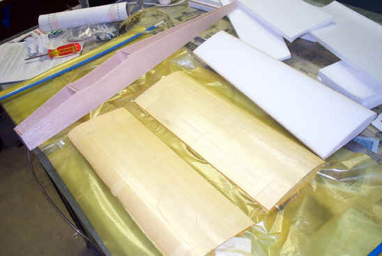
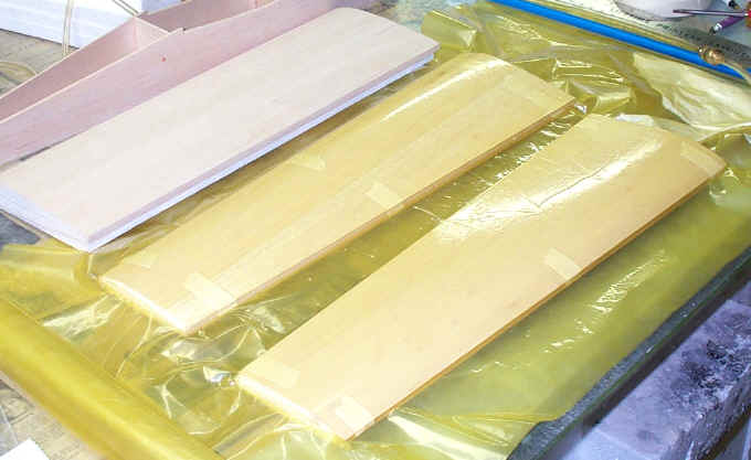
The Davis Akro Pro hybrid wing. This wing was designed to
incorporate the best of both types of construction (foam and built
up). There are advantages of both methods of construction that I liked so
I decided to construct a wing combining all of the good ones.
Built up wing advantages are lightness and the scale look of ribs
(depends on airplane). Foam wing advantages are mainly accuracy and
speed of construction.
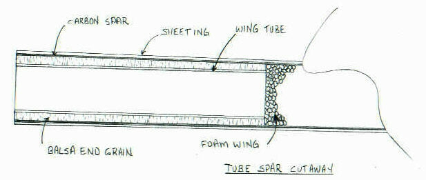
Once the core airfoil was cut I cut the tube hole and epoxied the tube
in place. After the tube was in place I cut a slot in the foam down to the
tube on the top and bottom to place the 1/4 inch end grain balsa. The
balsa was placed end grain to keep it from crushing and was capped with a
molded in carbon spar that sat flush with the foam core. A trough
was cut to accept the carbon tow and epoxy that extended from the root to
the tip. The carbon tow was gradually decreased in cross section towards
the tip, this was done to avoid a stress riser and to save weight. End grain balsa was also
added to the core where the aileron control arm would locate. (The
carbon spar and end grain tube caps cannot be seen since they are buried
in the foam but there is a rough drawing of the wing tube, end grain and
carbon spar below. This wing was built before this web site was even thought of
so this article is in retrospect).
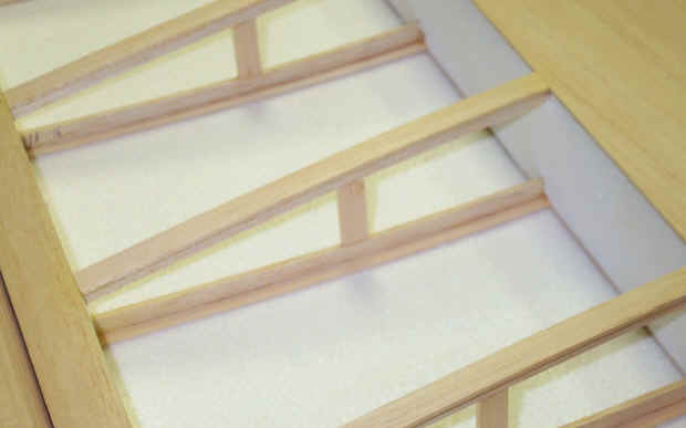
The grooves for the ribs were cut with a modified soldering iron tip
with a depth gauge attached. The wood strip ribs were added to the grooves
and glued to the spar after which they were sanded flush with the top
surface of the foam. This is where the real savings in time takes place
since the ribs do not have to be plotted or cut out. By placing the strip
ribs in the foam grooves you could literally place the ribs at any angle,
warren truss or geodetic construction could result effortlessly. If you
were building a wing where you didn't want any foam left you could run the
strip ribs between the leading edge and trailing edges with carbon fiber
reinforcements as a spar. Once you start thinking outside of the box many
options become available. The wood leading edge was glued to the leading edge
of the foam wing and shaped to match the contour of the airfoil.
The next step was to vacuum the sheeting that you see on the wing down
to the foam using epoxy as the adhesive. The sheeting overlapped the strip
ribs about 1/4 inch and completely overlapped the leading edge. By placing
the sheeting over the leading edge you gain some strength and hide a seam.
At this point when the wing is bagged there is still foam between the
false ribs. Once the wing was cured and taken out of the bag the
foam was removed from between the strip ribs and the vertical grain
supports are added between the top and bottom strip ribs. The rib caps are
added at this time to match the sheeting.
The back portion of the wing is cut away so that a full depth and full
span trailing edge (which goes in front of the aileron) could be added to
the wing. At this time the aileron was capped with a leading edge and
trailing edge along with the end caps. I wanted the trailing edge of
the wing that was in front of the aileron to extend the full span to get
away from a stress riser at the root of the aileron cutout on the wing.
The trailing edge of the wing at the root was also glued back on the wing
at this step.
For extra lightness the leading edge could be cored out after
bagging. All coring has to be done after the bagging process since
the cored wing will not hold up under any vacuum, tried that to see what
would happen, won't mention the results here.


 Joe
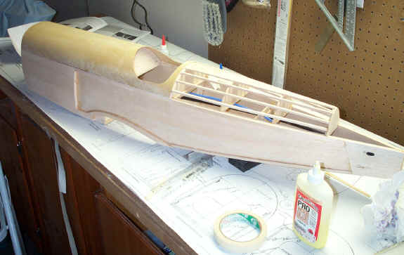
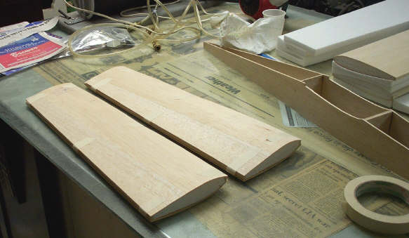
Hartley's Balsa USA EAA Bipe under construction. Balsa USA airplanes
employ conventional construction which Joe seems to favor. Notice the
aliphatic resin glue on the bench. Joe is going to power the EAA Bipe with
a Saito 100 and apply scale effects such as pinking tape and a dope
finish.
Joe
Hartley's Balsa USA EAA Bipe under construction. Balsa USA airplanes
employ conventional construction which Joe seems to favor. Notice the
aliphatic resin glue on the bench. Joe is going to power the EAA Bipe with
a Saito 100 and apply scale effects such as pinking tape and a dope
finish.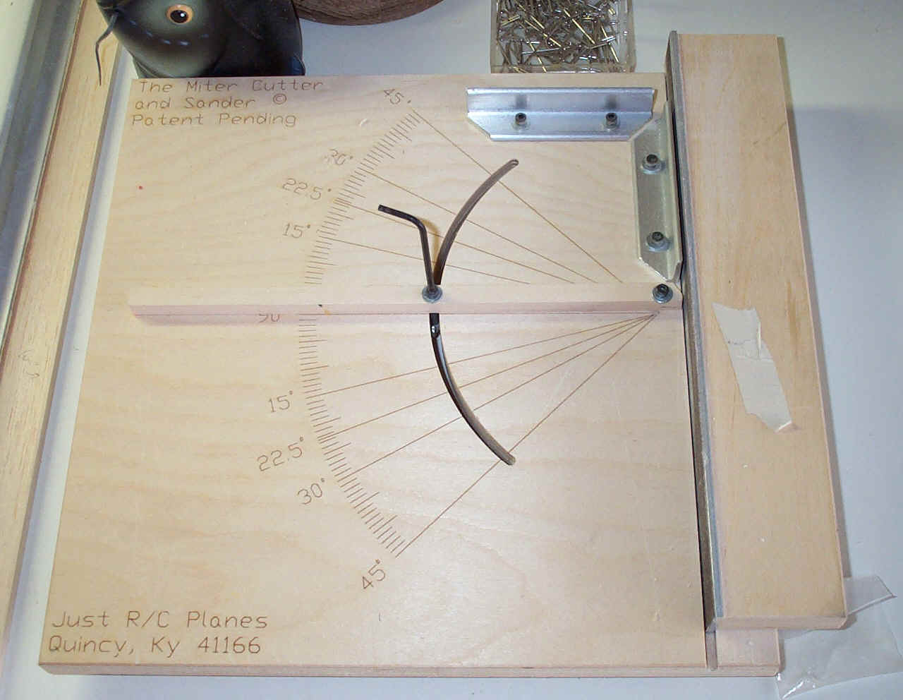 The
Miter Cutter
The
Miter Cutter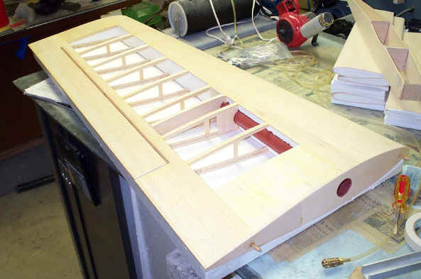
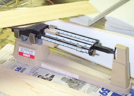 An Ohaus gram scale is invaluable for building light and
weighing epoxies etc. You can make good choices when you know what
the materials you are building with weigh. The scale pictured here weighs
in the tenth of a gram. Electronic scales are good but not as
accurate since they tend to round off to the nearest gram. This
scale never needs batteries either.
An Ohaus gram scale is invaluable for building light and
weighing epoxies etc. You can make good choices when you know what
the materials you are building with weigh. The scale pictured here weighs
in the tenth of a gram. Electronic scales are good but not as
accurate since they tend to round off to the nearest gram. This
scale never needs batteries either.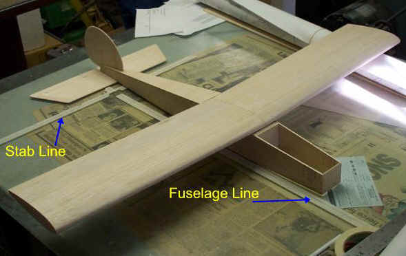 The
1/2 A Stick is coming along. Notice the cross hairs on the glass bench
top, they were drawn on masking tape with the aid of a carpenters square
and are used for alignment purposes. The plane is aligned according to the
lines drawn on the masking tape and not the tape itself. The leading edge
of the horizontal stab was aligned with the stab line and the fuselage was
aligned with the fuselage line running perpendicular to the stab line.
When the wing is ready to mount we will add another line to match up with
the trailing edge of the wing. When transferring a line from the table to
the trailing edge above the bench top a square will be used. The wing
incidence can also be set off of the glass bench top by measuring the
centerline at the tip from the glass. The beauty of this plane is
the way it can be assembled with the fuselage sitting flat on the bench.
The
1/2 A Stick is coming along. Notice the cross hairs on the glass bench
top, they were drawn on masking tape with the aid of a carpenters square
and are used for alignment purposes. The plane is aligned according to the
lines drawn on the masking tape and not the tape itself. The leading edge
of the horizontal stab was aligned with the stab line and the fuselage was
aligned with the fuselage line running perpendicular to the stab line.
When the wing is ready to mount we will add another line to match up with
the trailing edge of the wing. When transferring a line from the table to
the trailing edge above the bench top a square will be used. The wing
incidence can also be set off of the glass bench top by measuring the
centerline at the tip from the glass. The beauty of this plane is
the way it can be assembled with the fuselage sitting flat on the bench.