|
| |


 |
The Hybrid foam wing design is a variety of
techniques combined to create a wing that has all of the benefits that
built up and foam construction has to offer.
Foam wings have been around in modeling for some time and have seen
success in the winners circle in control line aerobatic airplanes along
with numerous R/C planes. The
weight of the finish product is dependant on three things, wood selection
(density), foam density (preferably 1# per cubic foot), and glue volume
and weight. The lamination adhesive was more often than not the reason for
overweight wings. |
| There are basically two types of glues used to laminate the
sheeting on to a foam wing, contact adhesives and standard types such as
epoxy and the new variety of pro bond types. I do not have any experience
using these pro bond type adhesives so I will not be able to offer any
advice concerning them. The people that talk of using them say they
work well. If used in conjunction with a vacuum bag they might be an alternative
to epoxy. I have chosen epoxy for it's weight savings and the fact that I
have gallon containers of various types in stock.
I originally used the contact type adhesives to apply sheeting such as
the 3M 77 and the Sig core bond and a variety of others. If you are
going to use any of these systems remember to do a compatibility test first
on some scrap. I have heard reports that 3M 77 has undergone a formula
change that attacks the foam. The drawback with these contact type of adhesives
was the weight. The 3M 77 was probably the lightest of all the contact
adhesives since you had good control of the amount applied. For the 3M 77
to work the two surfaces (wood and foam) had to be sprayed and the pieces
joined while the adhesive was still aggressively tacky. If the 3M 77 was
allowed to dry you lost the bonding action. Timing was very critical when
using this method. I found that you could get some of the 3M 77 on your
fingertips and keep touching the wood until your fingers don't want to
release from the wood as an indicator that it was aggressively tacky. Other contact adhesives would have to be dry before the
sheeting and foam could be joined. In some cases if the contact cement
wasn't dry you risked the chance of some of the solvents attacking the
foam. One of the major drawbacks of the brush on contact cements in my
opinion was the tendency to over apply the adhesive. About half of the
adhesive would end up between the foam beads where it served no other purpose
than to add weight. Although the contact glue method was heavier I still
had good luck with it holding up under the lifespan of the model which was
around five to ten years with some still going.
One advantage of the contact type adhesives was the fact that they were
quick. No need for weights and the cradles that the wings came in didn't
have to be straight since you would roll the wing down on the sheeting
which was sitting on a straight and flat workbench. Only one chance to
position here, once the wing came in contact with the sheeting it couldn't
be repositioned.
After a few years passed I started to experiment with composites and
fabricate some parts with various materials such as carbon fiber
fiberglass and industrial epoxies. The more that I worked with different
processes such as vacuum bagging the more I realized that the different
materials and processes could be
combined to compliment each other. Anyone in the manufacturing or
composite business will tell you that the PROCESS is the vital ingredient
in either success or failure. The process can vary greatly when the
quantity of items produced changes which is a subject for another web page
in itself. After a few test samples of vacuum
bagged balsa over expanded bead polystyrene were completed I was amazed
with just how little epoxy resin was needed to bond the wood to the foam.
There is a saying that states that a chain is only as strong as its
weakest link. So if the bond between the foam and wood is good enough or
strong enough to pull the beads of foam away upon delimitation then it's
strong enough. Adding expanding glue such ad pro bond that expands into
the beads just adds extra weight in my opinion. Remember that the beads
will still fail where the glue line ends so extending the glue deeper in
the foam just determines where it will fail without making it stronger in
my opinion. I also experimented with adding carbon veil under the sheeting
with success. Carbon veil was used on a R/C pattern wing in the
section of the ailerons for added rigidity.
Epoxy resin is only added to the sheeting. It is poured onto the wood
and spread with a scraper or spatula. Enough pressure is applied
while spreading the Epoxy to make the wood appear dry. My theory is that
there is enough epoxy forced into the grain of the wood to allow for
sufficient bond. Under vacuum the resin is drawn out of the grain to make
contact with the foam. The total amount of vacuum should not exceed
8 inches of mercury on 1# expanded bead polystyrene or you will crush or
distort the foam. Higher vacuums could be used on denser foams but
that would add unnecessary weight. In Control line Aerobatics we core the
wings out span wise to lighten them along with giving the leadouts a
tunnel to the bellcrank. I applied 8 inches of vacuum to a cored out
control line wing and the result was not pretty. If the hollowing cores
are slipped back into the wing the wing still distorts so the only
alternative is to core the wing out after vacuum bagging. By coring the
wing out after sheeting allows more foam to be removed than would be possible
otherwise. Even with all of these weight savings the wings were still not
as light as a built up wing. After all there is nothing in a wing as light
as air so the more air you can put in a wing the lighter it will be. After
cutting numerous foam wings I hated to give up on the speed of build,
stability and accuracy the foam wing presented so I decided to incorporate
all of the things I liked of each method (built up and foam) of
construction until I had the best of both worlds. The picture above
depicts my progress up to this point. |
|
Ok so you have this foam wing and you
want to make a hybrid wing from it so how do you go about it?
The foam wing in this method is used as a
three dimensional template so to speak. There are computer programs out
there that will plot and design rib sections at any angle and will figure
out any geometric problem that will arise. These programs are expensive
and have steep learning curves involved. Once the cost of the program is
overcome and you have mastered the program to produce the results you are
looking for you now have to incorporate the software into a machine to
produce the parts such as laser cutters or CNC routers etc. Once these
accurate parts are cut out then you need a fixture to hold these parts
together while gluing them. As stated above (the process can vary greatly when the
quantity of items produced changes) CNC machines, CAD programs and laser
cutters are invaluable tools for producing parts and designing but leave
these programs and machines to the people who are producing in large
enough quantities to justify their cost. Why design ribs on a cad
machine when you can drop wood blanks into slots in the foam wing and sand
to the right contour? The foam wing acts as a fixture to hold the strip
ribs while providing the exact contour regardless of the orientation of
the rib. |
|
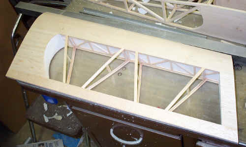
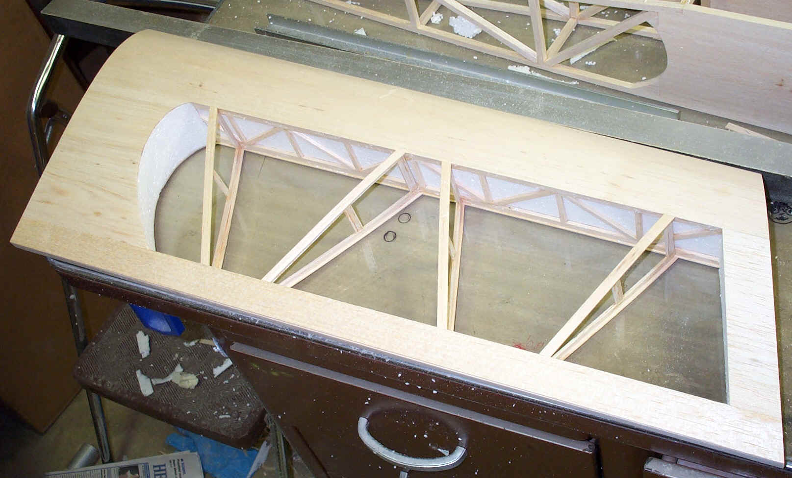
 This
picture shows the root of the wing in the top right corner of the picture.
The foam will remain in tact in this area. The full span built up spar was
installed in the first step where the wing leading edge was removed span wise
from the high point forward. The spar was tack glued in place between the
remaining wing sections fore and aft. There is no need to completely glue
the spar in place since the foam will be removed in future steps. A warren
truss construction was chosen for the spar since it is light weight and
strong. Don't worry about making the spar the exact depth of the wing. I
chose to make it slightly oversize (too tall) and sand sown to the height
of the foam wing leaving it sticking up a few thousands to make sure there
would be a good bond between the sheeting and the spar. The vertical
braces shown between the top and bottom ribs were added after the foam was
removed. This
picture shows the root of the wing in the top right corner of the picture.
The foam will remain in tact in this area. The full span built up spar was
installed in the first step where the wing leading edge was removed span wise
from the high point forward. The spar was tack glued in place between the
remaining wing sections fore and aft. There is no need to completely glue
the spar in place since the foam will be removed in future steps. A warren
truss construction was chosen for the spar since it is light weight and
strong. Don't worry about making the spar the exact depth of the wing. I
chose to make it slightly oversize (too tall) and sand sown to the height
of the foam wing leaving it sticking up a few thousands to make sure there
would be a good bond between the sheeting and the spar. The vertical
braces shown between the top and bottom ribs were added after the foam was
removed.
|
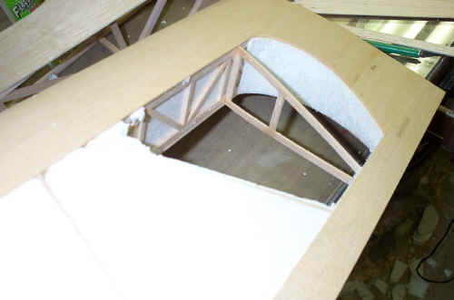
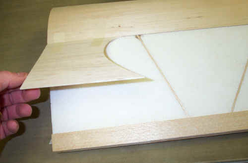
 The
leading edge was tack glued in place and sanded to conform to the shape of
the foam while leaving the front flat and squared off. The balsa leading
edge should follow the contour of the foam but not be radiused yet since
the sheeting will be bagged down over the top of it as shown here. Once
the spar and the leading edge are tack glued in you can start cutting the
slots for the ribs to go in. The
leading edge was tack glued in place and sanded to conform to the shape of
the foam while leaving the front flat and squared off. The balsa leading
edge should follow the contour of the foam but not be radiused yet since
the sheeting will be bagged down over the top of it as shown here. Once
the spar and the leading edge are tack glued in you can start cutting the
slots for the ribs to go in. |
 The
slots for the ribs to go into were cut with a soldering iron with a stop
set up for the correct depth. I chose to make my strip ribs about 5/16
deep. The depth of the ribs are dependant on the size of your wing. A See
Temp template was made up with the rib locations on it so that the top rib
would be over the bottom rib. the ribs can be positioned at any angle or
spaced at any interval since they become an exact duplicate of the wing
surface once sanded flush with the foam. By placing the ribs at an angle I
believe that the wing becomes a little less prone to twisting or torsional
stresses. Once the strip ribs are glued to the spar then the trailing edge
can be added. There are no ribs forward of the spar since the foam and
sheeting will provide the leading edge shape. The
slots for the ribs to go into were cut with a soldering iron with a stop
set up for the correct depth. I chose to make my strip ribs about 5/16
deep. The depth of the ribs are dependant on the size of your wing. A See
Temp template was made up with the rib locations on it so that the top rib
would be over the bottom rib. the ribs can be positioned at any angle or
spaced at any interval since they become an exact duplicate of the wing
surface once sanded flush with the foam. By placing the ribs at an angle I
believe that the wing becomes a little less prone to twisting or torsional
stresses. Once the strip ribs are glued to the spar then the trailing edge
can be added. There are no ribs forward of the spar since the foam and
sheeting will provide the leading edge shape. |

This picture was taken after the fact since you will
not have the leading edge or trailing edge sheeting in place at this time. |
 At
this point you should have the spar, leading edge, ribs and trailing edge
in place and ready to add the sheeting. The ribs should be permanently
glued to the spar and trailing edge at this time. The sheeting shown here
is vacuum bagged in place. Masking tape is used to hold things in place
prior to bagging. I vacuum bagged the sheeting in two steps. The first
bagging was for the leading and trailing edge sheeting and the center section
and tip sheeting were added in a second bagging. I wasn't sure I could get
all of the sheeting to line up correctly by bagging all of it at once so I
chose to be safe and do it in two steps. At
this point you should have the spar, leading edge, ribs and trailing edge
in place and ready to add the sheeting. The ribs should be permanently
glued to the spar and trailing edge at this time. The sheeting shown here
is vacuum bagged in place. Masking tape is used to hold things in place
prior to bagging. I vacuum bagged the sheeting in two steps. The first
bagging was for the leading and trailing edge sheeting and the center section
and tip sheeting were added in a second bagging. I wasn't sure I could get
all of the sheeting to line up correctly by bagging all of it at once so I
chose to be safe and do it in two steps. |
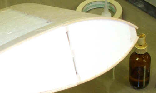
 The
wing after the foam has been removed from between the ribs. The leading
edge foam will be cored out span wise creating a D tube. The trailing
edge, wing root and tip will remain solid foam. By adding the tip sheeting
the wings torsional rigidity is increased substantially. The vertical rib
braces and rib cap strips are added after the foam is removed. This wing
is a Control line aerobatic airfoil that is going to be used on a sweet
stick. The fuselage in the rear of the photo is built up 1/4" sticks
aft of the trailing edge to save weight. The tail feathers are also
1/4" stick construction. It will be interesting to see how it flies
due to the light weight and increased control surface areas. There will be
a servo box constructed into the wing about 1/2 of the way out into the
panel. The
wing after the foam has been removed from between the ribs. The leading
edge foam will be cored out span wise creating a D tube. The trailing
edge, wing root and tip will remain solid foam. By adding the tip sheeting
the wings torsional rigidity is increased substantially. The vertical rib
braces and rib cap strips are added after the foam is removed. This wing
is a Control line aerobatic airfoil that is going to be used on a sweet
stick. The fuselage in the rear of the photo is built up 1/4" sticks
aft of the trailing edge to save weight. The tail feathers are also
1/4" stick construction. It will be interesting to see how it flies
due to the light weight and increased control surface areas. There will be
a servo box constructed into the wing about 1/2 of the way out into the
panel. |
|
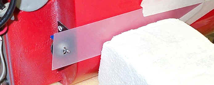
When it came time to mount the kill switch without the
proper cutout in the cowling I used See Temp as a guide for marking the
cowling. A cutout was made in the See Temp and placed over the switch. The
See Temp was taped in place aft of the cutout to the fuselage. The See
Temp was pulled back while the cowling was installed and marked for the
cutout. |
|
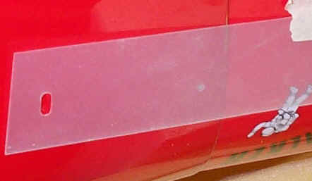 Mark
the cutout onto the cowling and cut hole for the switch. This is a neat way
to transfer cutout areas and have them line up exactly where you need
them. Mark
the cutout onto the cowling and cut hole for the switch. This is a neat way
to transfer cutout areas and have them line up exactly where you need
them.
|
|

|
| Here are a few balsa shells and their molds that were
molded by Steve Starr for his C/L stunter. One shell is the
turtledeck and one is the belly pan. The Article below is written by
a top control line flier Windy Urtnowski. For More Building Tips
Visit The Scratch
Building Reviews Page. |
|
MOLDED BALSA SHELLS
BY WINDY URTNOWSKI
Almost every type of model can benefit from parts
molded from thin sheets of balsa to form
"shells." This is especially true when light weight and
maximum strength are priorities.
A carved block offers very little grain-direction strength, but a
molded piece has excellent
strength derived from the grain.
Another benefit is that there is almost always a savings in time.
Carving a turtledeck or fuselage top from a solid block and then
hollowing it out is a common
way of building fuselage tops and bottoms. Unfortunately, not only
is the carving process
laborious and prone to error (who hasn't had a problem trying to
keep uniform wall thickness or
going through?), but also, the cost of large blocks of very
light-weight balsa is almost
unbelievable these days. Once you hollow the block, to make
another, similar ship, you would
have to carve another block over again, and of course, buy another
relatively expensive piece
of wood
On the other hand, you can turn a carved but as yet un-hollowed
block into a mold much more
quickly than it would take to hollow out the block.
You would have to buy the block and do the original carving either
way, but from that point on,
the choice is either to hollow or to spend a bit less time and
make a mold, with the advantage
of then being able to make as many parts as you like, quickly and
accurately, using inexpensive
sheets instead of expensive blocks. If you tend to build models on
the heavy side due to
"thick" hollowing techniques, you will benefit even
more.
At first, molding may appear difficult to do, but not long into a
project you realize that it's
almost always quicker to do than you first thought. After a few
trial runs, you can replicate
parts quickly, over and over, with very little effort. The
technique described in this article
has been easily adopted by many entry-level modelers in our club,
and in large clubs,
you may want to share molds for popular designs. We now have molds
for about ten very popular
designs, and they get used regularly.
So, if you think you'd like to try molding balsa, here are some
points that will help you
succeed right away and avoid pitfalls.
Some fuselages with complex or convex shapes may not be good
choices for your first attempt.
My Spitfire was molded in three separate pieces: nose section,
turtledeck, and one-piece
fuselage bottom. There were no radical shapes, so it was extremely
easy, and I made usable
parts on my first attempt. Following this technique, you should
have success right away,
and even if you don't, making corrections is very easy.
Let me take you through a typical fuselage top, as an example.
Build the fuselage up to the point of carving the top block.
Tack glue your block on and carve to final shape, but don't
final-sand yet.
Always try to use a fairly light-weight block to carve the
plug-it's easier to carve,
contour, and block-sand to final shape than hard balsa is. Four to
six-pound wood is ideal,
but six to eight-pound wood will work fine, with just a bit more
carving.
A trick scale modelers often use is to make female templates at
various fuselage cross-sections
to insure symmetrical side-to-side profiles.
Pop off the block now-you need to reduce its size slightly.
One effective way is to take a marker pen and "paint"
the wood surface.
Once you sand this off, you've under-sized the plug it by about
1/32 of an inch.
Depending on the thickness of your shell, you may want to repeat
this step,
but don't worry if you make it a bit too small-there's a trick I
found to fix that easily.
After the undersizing operation, lay the block back on the
fuselage, and you should see that
it's a bit smaller than the sides' width from end to end. It's not
critical at all, as the
finished shells are quite flexible and forgiving when final
installation time comes.
Originally, I'd mold right over this under-sized block, but
getting the right "edge" to fit
against the fuselage was difficult. Instead, here's a foolproof
way to do this accurately:
First, cut or sand a slight radius on the joining bottom edges of
the block.
Next, glue the mold block to a piece of half-inch balsa sheet,
then use a jigsaw to match the
outline of the carved block to the base piece-do this carefully.
Finally, glue a piece of 1/16-inch wire in each "joint"
between the mold block and the base,
where you created the radius. The wire will leave an impression in
the molded final shell,
showing the correct "trim" line. At this point, you're
already a few hours ahead of the guy
with a hollowing knife, and your mold is ready for a test to see
how accurate it is.
Molded balsa is actually very forgiving-to work well, fits don't
need to be as accurate as you
might think at first, and even if you demand perfection, it isn't
difficult to attain.
Select a sheet of 1/8-inch or 3/32-inch four to six-pound A-grain
balsa that will cover the
whole mold and the sides of the base when wrapped around.
(Use only A-grain sheets for molding parts-C-grain tends to
split.)
If you need to splice the sheet to make it wide enough, the glue
joints should go as close to
the edges as possible. Rough-trim the sheet so it does not go
beyond the edges of the base
when wrapped around.
Now, soak the sheet with ammonia, Windex, or water until it is
thoroughly soaked
(about five minutes). During this time you can pre-bend the sheet
around the mold by hand,
just to soften it up. Ammonia has a strong odor, so it's nice to
do this step in a garage or
outdoors, if possible. Windex and water should be used if you're
sensitive to ammonia smells.
They work almost as well as ammonia-just allow a little extra
soaking time.
You'll need a few Ace bandages to wrap the sheet tightly over the
mold-the best ones are the
kind that stick to themselves. They're available in a drug stores
and last forever.
I've found that the easiest way is to start wrapping in the middle
and work toward the end,
but you could start at the front and work toward the back, also.
The idea is to make
a "mummy," with the wrap reasonably tight all around.
Put a pin in the end of the wrap when
it's done, so it won't unwind while everything is drying.
Let this dry 24 hours with the bandage in place.
The next day, unwind the wrap, and peel the shell off carefully.
You'll see the impression of the wire on the inside face-trim off
the extra wood at this time.
I use an old sanding belt contact-cemented to my building table to
true up the shell edges
before installation. Once you're satisfied with the shell's fit,
it's ready for a final sanding.
Frank McMillan had a good tip: he recommends doing most of the
sanding of a shell on the mold,
for best results. This works great, and I recommend it.
If the shell is too big, sand down the mold some more and make
another shell.
If it's too small, you can put layers of masking tape on the mold,
or a sheet
(or two) of 1/32-inch under your next mold sheet and mold the
1/32-inch and 1/8-inch at the
same time to make a slightly larger shell. This also allows one
mold to yield several sizes
of shells for different designs.
About the time you're finished molding, you're even with the guy
who's hollowing,
but you can now make as many parts as you like, every one
straight, true, and of
uniform wall thickness. Keep in mind that the same mold can make
parts that will fit
similar-sized ships. For instance, my Spitfire turtledeck mold
makes a perfect Nobler
top-rear shell. Most nose molds are similar and interchangeable,
so once you do a few sizes,
you can make custom shells for almost every model.
Another technique is to laminate several layers of 1/32-inch sheet
with glass cloth or
carbon fiber veil between the layers. First, do all the shaping by
molding three or four
pieces right on top of themselves, all at once. Once they're
shaped and dried, separate
the sheets, and using slow-cure epoxy, sandwich the layers of
glass or carbon fiber veil
in between, on the mold. A good tip here is to wrap the mold with
Saran Wrap to prevent
any of the squeezed-out epoxy from sticking to the mold. The Ace
bandage pressure will
squeeze out almost all the extra resin, making an extremely
strong, extremely light part.
On complex designs, you may want to add laminations of 1/32-inch
sheet inside the shell,
especially where it butts up to the spinner ring. Adding cooling
vents of 1/64-inch molded
plywood is a nice touch, too. Use a piece of tubing for the mold,
soak the plywood, and
wrap it in the direction opposite to the grain of the outer
lamination.
To install a finished shell, I glue about six inches at a time
with CA, alternating
sides and checking that things are staying aligned, then run a
bead of CA down the
seams on the inside and fine-sand the final exterior joints.
I videotaped the whole molding operation for modelers who'd like
more information.
The tape is a full two hours long and is available from John
Brodak.
Once you've installed your first shell, look over at that mold and
smile, because
building your next ship will take a fraction of the time, and with
the money you save
by not having to buy another block, you can take your wife out for
pizza.
Using this technology, you'll quickly see other parts that lend
themselves to molding.
Turtle decks, wing tips, leading edges, hollow rockets, bombs-the
ideas are limited only
by your creativity. When Joe Adamusko and I did our Spitfires, we
pre-molded the leading
edge sheets of the elliptical wings. You can even take an old wing
and use it to mold
leading edge sheeting, or just carve out a mold piece from
styrofoam.
I've made wrapped stabilizer and rudder leading edges, and
hollowed rockets for my F-16.
Once you run off a few parts, you'll have ideas of your own, too.
It's a modeling technique you'll find many unique uses for. |
|
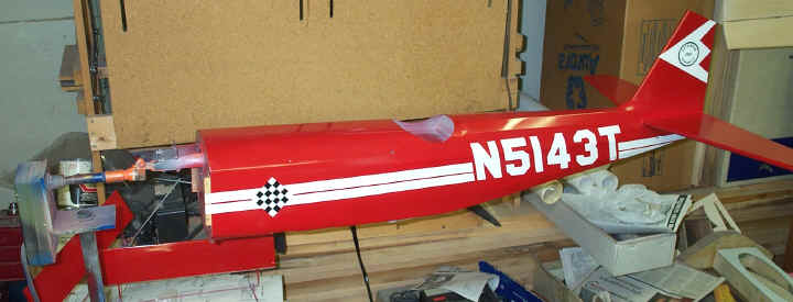 |
| Fuse Painting fixture
complements of Steve Ragsdale. Steve used a rotisserie grill motor for his
fixture rotation. Steve went so far as to install a foot switch to rotate
the airplane. When you see a run coming on you just step on the switch and
keep her turning. The motor can also be turned by hand and the gears in
the motor holds the plane in position without rotating. I have used this
fixture to paint the fuse all the way from the first coat of dope to the last
clear coat. Masking was also done on the fixture. All of the
graphics are painted with the exception of the round logo on the vertical
stab. The type in the decal were just too small to paint. Tutorial on how to paint
checkers and apply Ultra Coat
checkers of all shapes and configurations CLICK
HERE. |
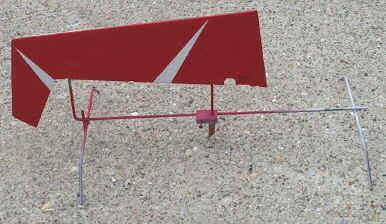
| Since
the control surfaces of the Citabria are applied to the model after painting
there had to be some way of holding these parts. I made some fixtures
years ago for my control line models that were adjustable enough to work on a
variety of shapes and configurations. The fixtures were constructed from
1/8" music wire with Delrin slider blocks with 4-40 set-screws to adjust
the spacing of the uprights. The upright coming out of the Delrin block
has a tab to insert into a flat hinge slot. The Citabria utilizes Robat
Hinge Points so the 1/8" music wire was inserted into the hinge holes.
The fixtures used for the ailerons are the same except for the length. |
 |
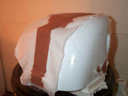 |
The Balsa USA Citabria cowling is ABS plastic and is used as a plug to make a
mold for a fiberglass cowling. Before the cowling is suitable for a plug
it has to be reworked. The seams of the ABS cowling sink in and need to
filled with epoxy and micro balloons. Phenolic micro balloons are used
hence the red color. (Glass micro balloons are white). Once the micro mix has
been applied to the seams and low spots a peel ply is applied to the micro
mix. The peel ply allows you to work the filler down and spread with your
gloved fingers. The peel ply used here is the good old Sig Koverall. Since it
is a polyester fabric epoxy will not adhere to it. Once the peel ply is
removed then the micro mix is sanded to blend in with the rest of the
cowling. This might take a few applications before the cowl is suitable
for a plug. Peel ply also leaves a bondable surface on those projects that
require secondary bonding. |
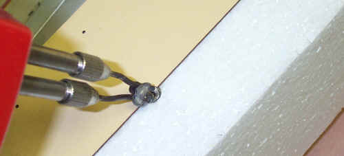
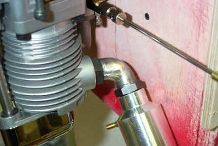
| The
modified Saito header. I ran in to a problem with the header positioning
the muffler too far aft so as to interfere with the firewall. Since the
belly pan came up to the firewall the firewall cut out option was out of the
question. Flex pipe would work but that would mean having to mount the
muffler to keep it from flopping around. The alternative you see here is a
braze joint. A pie wedge was cut out of the inside section of the header
bend. Once the extra material was removed from the inside bend of the
header it was bent together thereby closing the gap and brazed. The material on
the outside of the bend is adequate to strengthen the joint
(hopefully). I am happy to report that as of 11-14-01 after about two
gallons of fuel that the header is holding up fine. |
 |
|