|
| |

|
This page will cover the application of composites in
model airplanes and ways to utilize carbon fiber and fiberglass in model
airplanes. This page consists of my personal experience with composites
and is by no means definitive. |

|
Common Mistakes
One of the most common mistakes that I have noticed when
a carbon fiber or fiber glass part is designed is the tendency to
fabricate it in the same shape as it's metal or previous counterpart. This
is especially evident in landing gear where the gear is molded to the same
dimensions as its metal counterpart. By making a composite landing gear
flat one can speed up the production process but you loose out on rigidity
and weight savings. When a composite landing gear is constructed with
carbon or glass fabric bagged into a female mold resembling a gutter
all of the fiber that is running the chord of the gear is adding weight
and contributing no rigidity. Since the gear is flat, rigidity is also
compromised. The solution to this problem is to make a carbon fiber gear
that has a teardrop cross section with unidirectional tow running the
length of the gear. By creating a teardrop cross section you increase the
strength and rigidity of the gear while lowering it's weight. When the
gear is molded with a teardrop cross section only one can be made at a
time due to the mold configuration thereby compromising production speed
and simplicity. Carbon cloth or Kevlar can be added to the leg of
the gear where the axle is mounted and where it is mounted to the fuse to
offer splitting resistance.
Ever see that iron on carbon tow? That spider web glue
that melts when heated is only there to keep the fibers oriented and
together while making a preform. A preform is made to fill a closed mold
while the resin is injected or pulled through the mold by vacuum thereby
wetting out the preform. The tow is not made to be ironed on without any
other resin added.
Some thoughts on core materials. The use of core
materials can be very advantageous. When core material is used to double
the thickness of a structure, the relative stiffness increases 7 times.
The strength increases 3.5 times while the weight only increases 1.03
times. When core material quadruples the thickness, the relative stiffness
increases an incredible 37 times, the strength increases 9.2 times, but
the weight only increases a mere 1.06 times.
When glassing the center section of a wing orient the
fiberglass cloth so that both the warp and fill cross over the center
section seam. Warp is the tow that is running lengthwise in the woven
fabric and fill is the tow that runs across the roll of cloth. By
orienting the cloth so that both the warp and fill cross the center
section you are doubling the strength for the same weight. By using a low
viscosity resin for glassing the center section of a wing and extending
the resin a little past the fiber glass will create an edge to sand
against while blending the glass into the wing. |
|
Resin Overview
All epoxy is not created equal. There are literally thousands of
combinations of resins and curing agents available to the fabricator.
The fabricator is not only responsible for making the part but also
creating the material that the part is made from. There are many
resin manufactures that have proven resin and curing agent combinations
available. A good understanding of the cured and uncured properties
of these resins and curing agents will allow the fabricator to make the
right choice when choosing the resin. The choice of resin is
dictated by the parameters that you want the resin to operate in.
Bellcrank and mold.
Polyester is not a structural resin
 | Polyester is ok for car repair and non structural
uses (tanks, bins, bathtubs) Lowest cost, highest production
rates (very fast cure rates) Won't work on polystyrene foam (it
softens the foam) Heavy, and hard to obtain proper fiber resin ratios
due to wet out properties. Good secondary bonds are hard to obtain.
Poor bond to Kevlar. Bondo and Featherfill are polyester-based. |
Vinylester is similar to polyester
but has better structural properties than polyester
| Better bond to Kevlar and Carbon fibers than
polyester. Gel time can be extended to 10 hours. Mid-cost,
still less than epoxy. |
Epoxy is the material of choice
for structure
| Cure cycles pace production work. Health
hazards are present. Costly materials. Oven cure varieties
are available to allow large lay-ups. Many varieties to match
specific structural requirements. |
General considerations for all resin
systems
| Health hazards. Workability. Cost.
Chemical resistance (fuel proof). Compatibility with
fibers and core materials. Required service temperature and
moisture environment. Fabricator must understand the materials
they are working with. Clean up issues and hazard waste. |
Resin Matrices
Polyester
| Cures by polymerization (long parallel molecular
chains). Lowest cost resin. Unsuitable for structural
lay-ups, low properties. Limited to low temperature
applications. Insensitive to mix ratio (amount of catalyst
affects cure rate not material strength) High shrinkage
(unstable parts/tools, cloth print through) Polyester part will
not bond to a epoxy part. Contains styrene; therefore cannot
apply over polystyrene foam. |
Vinylester
| Improved version of polyester resin, better
properties, higher cost. Less health risk than epoxy.
properties are between polyester and epoxy. Extended pot life to
allow larger lay-ups |
Epoxy
| Most common structural resin, many different
varieties available. Cures by cross linking (three dimensional
process). Very sensitive to proper mix ratio of resin to
hardener. In the small batches that are used in modeling a
Triple beam gram scale is needed. Highest cost. Room
temperature or oven cure variants available. Absorbs moisture
(hydroscopic). Oven cure variants have higher Tg and Heat
Distortion Temperatures. Will bond to a polyester part.
Multiple health issues. Lowest shrinkage (highest stability).
Excellent adhesive properties (good secondary bonds). Face coats
available for tooling surface finishing. Laminating and tooling
resins available. |
Epoxy Resin Specifications
| Mix Ratio: by weight (most accurate) or by volume.
Typical ranges 100:44 to as low as 100:5 by weight. When mixing small
quantities for model airplanes a triple beam gram scale that measures
in 1/10 of a gram is required. |
| Mixed viscosity, low viscosities required for
laminating resins to ensure proper wet out, high viscosity for tools.
A good viscosity for a hand lay-up is around 500 to 800 centipoise. |
| Pot Life, 100 gram mass; larger masses cure faster,
pot life characteristics limit the maximum laminate thickness possible
per cure cycle. Oven cure resins have extended pot lives, allowing
larger lay-ups to be accomplished. Most resins for a propeller
or similar size part would require only 20 to 25 grams of resin.
Mixing more than you need decreases the pot life and wastes resin. |
| Pot Life for thin film: More representative of time
available to wet out laminate and bag if required. 100 gram mass pot
life is representative of a small batch mix according to the resin
manufactures. Actual pot lives are even less then specified when
thixotropics are used. Thixotropics include micro balloons,
flox, Cab-O-Sil and chopped carbon fibers. |
| Gel Time: Similar to pot life; resin is too
thick to wet out fibers once gelled. |
| Cured Hardness, Shore D: Cured resin can be hardness
tested to assure full cure. When making a part it is important
to save the left over epoxy in order to test the cure. |
| Glass Transition Temperature (Tg): Maximum
temperature at which resin properties diminish appreciably, sometimes
referred to the resins "red line" temperature. When a
cured polymer is heated, vast changes in thermal and mechanical
properties occur. These changes are particularly large near the
glass transition temperature, Tg. Below the Tg, the polymer is
hard and glassy, and above the Tg it has a rubbery state. At
this temperature, tensile strength, hardness, electrical properties
and chemical resistance depreciate rapidly, while tensile elongation
and flexibility increase markedly. Tg usually occurs over a
range of temperature, but for simplicity a single temperature is
selected as Tg. |
| Heat Deflection Temperature (HDT): Temperature at
which the resin begins to soften but still has good structural
properties. The deflection temperature is commonly used as
approximation of Tg. The method for measuring DT has been
standardized by ASTM. The DT is determined on a casting which
has been permanently stressed at (264 psi) by flexural loading and
then heated at a constant rate until the casting deforms a specified
amount. The DT method usually requires a larger sample than Tg
methods. |
| DT's and Tg's provide a measure of crosslink density
of the polymer. Those polymers with higher DT's have higher
crosslink densities, better performance at elevated temperatures and
generally better solvent and chemical resistance. The choice of curing
agent and the cure cycle (degree of cure of the polymer) are the
largest factors affecting DT. You would want a higher Tg resin
on a tuned pipe than on a wheel pant. |
| Notch Sensitivity (Izod Impact): A measure of
the resin's brittleness. A water ski would require a resin that
is a little more flexible than a model airplane propeller blade. A
plasticizer can be added to make the resin tougher and less prone to
fracture. |
| Post Cure: The manufacture's recommended
elevated temperature cure cycle to be used to attain the best material
properties. Post cures either follow a room temperature cure or
an intermediate temperature oven cure for oven cure materials. Free
standing post cures are typically successful if a gradual ramp up in
temperature is used. High-temp assembly fixtures are required if
a free-standing post cure cannot be accomplished. |
| Peak exotherm, Fahrenheit: An indication of a resin's
likelihood to exotherm uncontrollably. The chance of exotherm can be
reduced by limiting mix batches to small quantities, proper disposal
of leftover resin, and knowing your resins properties (testing).
Exotherm is a term used to describe the internal heat generated by the
cross linking of the resin to the hardener. On some resin
hardener combinations a 50 gram mass is great enough to melt a plastic
cup and become hot enough to burn your skin. Larger quantities create
a fire hazard. |
| Resin "Physicals" Include: Density,
Hardness, Viscosity, Elongation, CTE or coefficient of thermal
expansion, Tg, HDT, Pot life, Mix Ratio, Color, Peak Exotherm,
Shrinkage, Izod Impact and others. |
Back to
Top
Materials
Carbon Fibers
| Carbon fibers, Though known since
Thomas Edison's development of the incandescent light in the 1870s,
were not made in large quantities until the late 1960s. At that
time it was found that carbonizing several fibrous materials resulted
in a continuous fiber with relatively low density and high Young's
modulus of elasticity. Modulus of elasticity is a parameter indicating
a material's stiffness. Young must have been the one who came up
with a mathematical way to measure this. High modulus materials
are stiffer than low modulus materials. |
| Fiber Sizing : Sizing are added to fiberglass and carbon fiber to aid
in processing and to allow the resin a better bond to the fiber. Silane
coupling agents are a used as adhesion promoters. While the sizing helps
in the processing of fibers they can hinder wet out of the fabric or tow.
Carbon fiber sizing must be applied to the fiber tow (which may consist of
12,000 filaments of more) to prevent the individual filaments from contact
damage between themselves or with eyelets or guides during weaving or
prepreging. When using tow to manufacture propellers and bellcranks it was
necessary to massage the tow in order to loosen the sizing for better wet
out. The thing to remember when ordering carbon fiber and fiber glass is
that the sizing is compatible with the type of resin you are using. Some
sizings in the fiber glass industry are for polyester only but most
sizings are for both epoxy and polyester resins. One can obtain a discount
on fiberglass with expired sizing when ordering from the mills in
large quantities.
|
| If you have ever handled carbon tow
in the raw state without sizing it is very soft. Fabricators
rely on its tensile strength for the parts rigidity. It is of
great importance to keep the fibers in line with the loads being
applied to it for the best strength properties. Even the crimp
in a carbon tow that allows the tow to be woven into a cloth weakens
the material. This is why unidirectional carbon lay-ups tend to
be the strongest. While talking to Hiroshi Kiyomoto who
fabricated Kaz Minato's carbon wing of his latest Blue Max at last
years Nationals he stated that he used unidirectional carbon in the
wing. One layer was from root to tip and the other was from the
trailing edge to the leading edge. By doing this he could obtain
a stronger lighter wing than would have been possible with a carbon
cloth. Carbon cloth holds excess resin in between the tows if
not compacted with a vacuum bag. Carbon cloth greatly speeds up the
production process though. |
| While carbon fiber is considered a
light weight material in the full size world, it still remains a great
challenge to save weight on a model airplane with this material.
If you are trying to replace 4 to 6 pound per cubic foot balsa with
carbon fiber the results are usually disappointing. The tools to
achieve the proper compaction are out of the hobbyist's range. These
tools are autoclaves and composite ovens. It's still hard to beat a
good piece of 4 1/2 pound balsa for formers, ribs and the like.
Carbon fiber excels on the materials normally constructed from
hardwoods, metal, plastic etc. or high stress areas such as spars and
the like. |
| One of the biggest obstacles to
overcome when designing a part from composite materials is the natural
tendency to copy a part exactly as if it were made from its previous
material. The part should be redesigned to take advantage of the
formability and strengths of the composite material. A composite part
should not be limited to the shape of a metal or plastic part. |
| There are three types of carbon fiber, Rayon,
Polyacrylonitrile (PAN) and Pitch. |
| Rayon precursors, which are derived from cellulosic
materials, were one of the earliest precursors used to make carbon
fibers. The processing disadvantage was a high weight loss, or
low conversion yield to carbon fiber. Typically only 25% of the
initial fiber mass remains after carbonization, which means that
carbon fiber made from these materials is comparatively more expensive
than carbon fibers made from other materials. |
| Polyacrylonitrile (PAN) precursors are the basis for
the majority of carbon fibers commercially available today. They
provide a carbon fiber conversion yield that is 50 to 55%. These
precursors can be thermally rearranged before thermal decomposition,
which allows them to be oxidized and stabilized before the carbon
fiber conversion process, while maintaining the same filamentary
configuration. The chemical composition of PAN precursors
defines the thermal characteristics that the material displays
throughout the oxidation/stabilization portion of the conversion
process. These thermal characteristics influence the processing
sequences that are used to convert PAN precursors to carbon fiber.
Carbon fiber based on a PAN precursor generally has a higher tensile
strength than a fiber based on any other precursor. This is due
to a lack of surface defects, which act as stress concentrators and,
hence, reduce tensile strength. Carbon propellers and bellcranks that
are made by Winship Models utilize PAN based carbon fiber. |
| Pitch precursors based on petroleum asphalt, coal
tar, and polyvinyl chloride can also be used to produce carbon fiber.
Pitches are relatively low in cost and high in carbon yield.
Their most significant drawback is nonuniformity from batch to batch. |
Glass Fibers
| There are literally thousands of fiber glass
fabrics and tows available to the fabricator. For modeling use the
varieties of fabrics under 2 ounces per square yard are the most
common. |
| E- Glass is the most common (and least expensive)
grade of glass fiber. |
| S -Glass is a special grade of glass that is much
stiffer than E-glass and somewhat stronger. |
| The use of fiber glass on a stunt ship is usually
limited to the center section of a foam wing or around the nose
section, either on the outside or for reinforcement around the nose
formers. If using fiber glass to strengthen the center section
of a foam wing keep the glass fibers running at a 45 degree angle to
the center wing joint. This will allow both the warp and the
fill fibers of the cloth to span the wing joint giving double the
strength with no weight penalty. The warp direction is the
direction of the long fibers as the cloth is pulled off of the roll.
The fill fibers are the fibers that run side to side as the cloth is
pulled off of the roll. |
| Almost all glass cloth has sizing applied to it to
aid in resin wet out and adhesion. Some sizings are for polyester
resins and some are for epoxy resins. If the glass cloth or
tow has the wrong sizing for the type of resin used, then the bond
will be weak between the resin and cloth or tow. While this
might not be of great concern on a pair of wheel pants it might
prove to a problem if a speed prop was constructed without the
proper sizing applied to the tow. Usually a fiber glass that
is not properly wet out will have silver of white streaks or spots
in the laminate. |
|
 I
decided to make a carbon fiber landing gear for the Midwest Extra 300 to
save a little weight. The carbon fiber landing gear should cut the gear
weight in half over the aluminum component. I
decided to make a carbon fiber landing gear for the Midwest Extra 300 to
save a little weight. The carbon fiber landing gear should cut the gear
weight in half over the aluminum component.
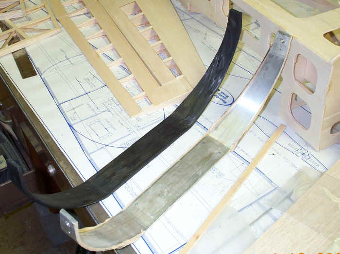
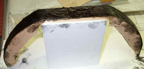
I am using the original gear for the mold. This gear is
a one off so if more than one gear was to be made a matching face mold
would be constructed. The landing gear is mounted to foam blocks for easy
layup. Along the edge of the aluminum there is a balsa dam that is
1/4" above the gear. The height of the balsa edge above the gear will
determine the thickness of the gear. This balsa edge will hold the
carbon fiber on top of the gear while the layup is in progress also. I
will attempt to sand in some teardrop shape to make the gear more
aerodynamic after demolding. Clear packing tape was placed over the
predrilled holes to keep the resin and carbon from running through them. A
Freekote 700 mold release was also used to assure the carbon gear would
release from the aluminum gear. |
|
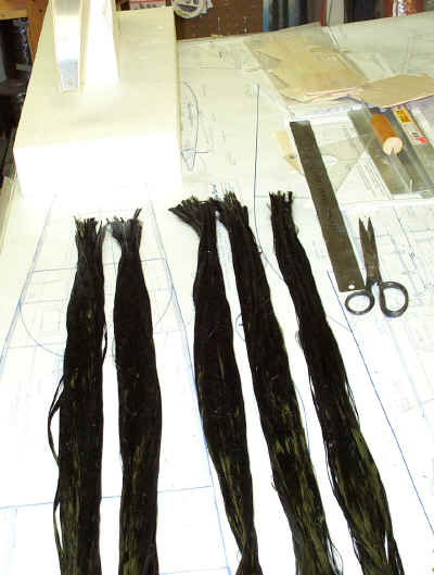 The
carbon tow has been cut to length and is now waiting for the resin. I am
not sure how many filaments there are since it is not important due to the
fact that every gear will require a different amount of carbon fiber. I
guessed on the amount by placing the carbon tow in the mold to see how
much it would take to fill it. I guessed pretty close since didn't
need to cut additional carbon. The tow was cut a few inches oversize and
was trimmed where it hangs over the end of the gear. The carbon tow
trimming was them placed in the center of the gear The
carbon tow has been cut to length and is now waiting for the resin. I am
not sure how many filaments there are since it is not important due to the
fact that every gear will require a different amount of carbon fiber. I
guessed on the amount by placing the carbon tow in the mold to see how
much it would take to fill it. I guessed pretty close since didn't
need to cut additional carbon. The tow was cut a few inches oversize and
was trimmed where it hangs over the end of the gear. The carbon tow
trimming was them placed in the center of the gear
|
 The
carbon tow was wet out on wax paper before placing in the mold. With this
much tow and resin it is a good idea to work fairly fast since the pot
life of the resin is dependant not only on room temperature but the mass
of resin. If the resin is spread out onto the tow you will avoid an
exotherm and increase the working time. The mold was filled to the top or
a little over and will be sanded down to the proper thickness after
curing. The balsa sides will be sanded off after the gear is sanded or
ground down to the height of the balsa. A mid temperature resin was used
that has a heat deflection temperature of 260 deg. F. after post cure. A
high temp or mid temp resin is mandatory for a landing gear in my opinion
since the heat radiating off of blacktop in the summer can reach as high
as 120 deg F. in Indiana. The high temp resins also have greater
structural properties. There are many landing gears that are constructed
by laminating layers of carbon cloth over or in a mold but the carbon
fiber that is running chord wise in the mold is not providing any rigidity
and adding unnecessary weight. If you desire greater strength at the
wheel/axle attachment point you can bond on a piece of carbon fiber woven
plate for splitting resistance. Unidirectional carbon fiber tow is the
strongest and lightest way to make a landing gear and since the original
landing gear can be used as the mold it makes it affordable for the person
who would like a starter carbon fiber project. If for some reason you
still want to use the original landing gear you will be able to after removing
the carbon part provided you do not forget the mold release. The
carbon tow was wet out on wax paper before placing in the mold. With this
much tow and resin it is a good idea to work fairly fast since the pot
life of the resin is dependant not only on room temperature but the mass
of resin. If the resin is spread out onto the tow you will avoid an
exotherm and increase the working time. The mold was filled to the top or
a little over and will be sanded down to the proper thickness after
curing. The balsa sides will be sanded off after the gear is sanded or
ground down to the height of the balsa. A mid temperature resin was used
that has a heat deflection temperature of 260 deg. F. after post cure. A
high temp or mid temp resin is mandatory for a landing gear in my opinion
since the heat radiating off of blacktop in the summer can reach as high
as 120 deg F. in Indiana. The high temp resins also have greater
structural properties. There are many landing gears that are constructed
by laminating layers of carbon cloth over or in a mold but the carbon
fiber that is running chord wise in the mold is not providing any rigidity
and adding unnecessary weight. If you desire greater strength at the
wheel/axle attachment point you can bond on a piece of carbon fiber woven
plate for splitting resistance. Unidirectional carbon fiber tow is the
strongest and lightest way to make a landing gear and since the original
landing gear can be used as the mold it makes it affordable for the person
who would like a starter carbon fiber project. If for some reason you
still want to use the original landing gear you will be able to after removing
the carbon part provided you do not forget the mold release.
Also in the pipeline
is a plug tutorial for a pattern plane.
|
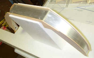
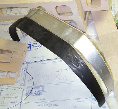 The
carbon gear has finally been released from the aluminum landing gear. Some
of the balsa side structure is still stuck to the aluminum gear but can be
removed by sanding. The
carbon gear has finally been released from the aluminum landing gear. Some
of the balsa side structure is still stuck to the aluminum gear but can be
removed by sanding.
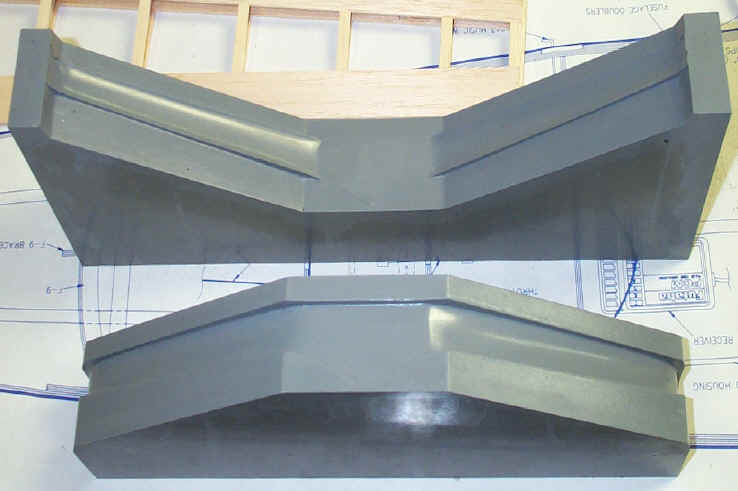
The carbon fiber gear in the picture has been sanded to
a teardrop shape and is constructed entirely from carbon tow. I feel that
a secondary bond of some carbon fiber woven plates at the axle attachment
would be beneficial.
The aluminum landing gear weighs 347g or 12.23 ounces
and the carbon gear weighs 229g or 8.07 ounces for a total weight savings
of 4.16 ounces. The carbon fiber gear at this weight is stiffer than the
aluminum gear and could be made lighter. Since the carbon gear was formed
over the aluminum gear it is slightly taller and wider which I feel is beneficial.
If these composite landing gear were going to be mass produced a matched
mold would have to be constructed to form the cross section of the
gear.
Since I was only going to make one of these landing
gears I used the TLAR (That Looks About Right) Engineering process. After
making numerous parts from carbon tow I had a good idea of the amount of
tow it would take to fill the mold and was able to pre cut the right
amount. If making these landing gears from a matched mold one would need
to keep track of the amount of resin and tow in order to completely fill
the mold. There are production processes available such as VARTM (Vacuum
Assisted Resin Transfer Molding) that would be suitable to producing parts
with this geometry economically. VARTM processes will be covered in
the future although the process isn't cost effective for only one or two
parts.
 Thumbnail of the bottom of the Extra 300 carbon fiber landing gear.
 Thumbnail of a carbon fiber control line landing gear mold.
The mold is a matched die type mold and is the type of mold used when you
want to produce a carbon gear that has a streamlined cross section.
Thumbnail of a carbon fiber control line landing gear mold.
The mold is a matched die type mold and is the type of mold used when you
want to produce a carbon gear that has a streamlined cross section.
|
 When
I started to mount the kill switch on the Spacewalker I realized that I
needed a right angle bracket to mount the switch. The bracket material was
fabricated from six layers of carbon cloth with four layers of glass
acting as a core. Since the bracket wasn't going to carry a load the fiber
orientation wasn't critical. The bracket could have been made of wood but
the light weight and compact nature of the carbon fiber bracket was
appealing. When
I started to mount the kill switch on the Spacewalker I realized that I
needed a right angle bracket to mount the switch. The bracket material was
fabricated from six layers of carbon cloth with four layers of glass
acting as a core. Since the bracket wasn't going to carry a load the fiber
orientation wasn't critical. The bracket could have been made of wood but
the light weight and compact nature of the carbon fiber bracket was
appealing.
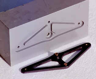
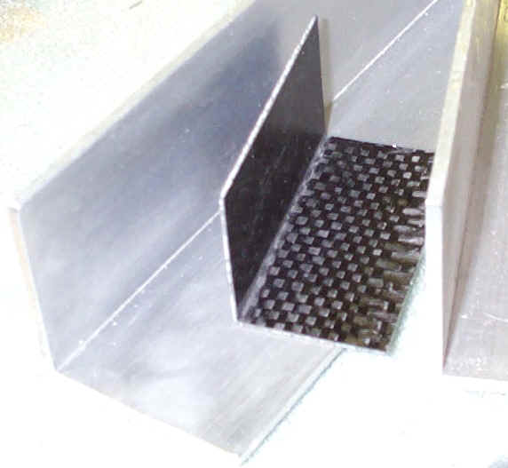
The picture shows the aluminum angle that was used as a
mold. I sanded the aluminum to remove the dirt and lightly polished the
surface before applying the Freekote mold release. The laminate in the
picture has been trimmed and the actual switch mount has been cut away
from the part shown. Since making these brackets are relativity easy I
made a piece large enough to cut multiple brackets from. After the part
was laid up an oven cure of 150 degrees F for four hours the part was
demolded and trimmed. A 250 degree F resin was used but since the part
wasn't going to see that high of a temperature a 150 degree F was
adequate. C clamps provided the pressure to debulk the laminate. |
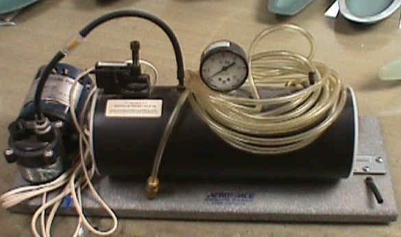 Pictured
here is a vacuum pump sold by Aerospace Composites. The pump will pull
about 18Hg. This pump is an excellent vacuum source for bagging balsa to
foam since the vacuum can be adjusted. When bagging expanded bead
polystyrene you will need to stay under 7Hg to keep from crushing or
distorting the core. The other advantage of this pump is the vacuum Pictured
here is a vacuum pump sold by Aerospace Composites. The pump will pull
about 18Hg. This pump is an excellent vacuum source for bagging balsa to
foam since the vacuum can be adjusted. When bagging expanded bead
polystyrene you will need to stay under 7Hg to keep from crushing or
distorting the core. The other advantage of this pump is the vacuum |
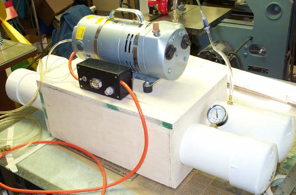 THE
BIG SUCKER THE
BIG SUCKER
This is a composite de-bulking vacuum system that was
built similar to the one shown above except that it is an industrial
version. The Gast pump is rated a 1/3 hp and will pull 28Hg. This
composite vacuum pump is well suited for vacuum bag mlding. The two PVC
schedule 40 pipes provide the vacuum tanks and are inserted into a wooden
box that acts as a motor mount and tank holder for the Gast pump which
sits on four Lord Mounts. The black project box was purchased from Radio
Shack to hold the relay, switch and fuse. The vacuum switch, relay, vacuum
gauge, check valve and miscellaneous fittings were purchased form
Aerospace Composite Products. George Spar sells a new vacuum switch that
is adjustable over the full range of vacuum from 5Hg to 28Hg. The vacuum
switch and 10 amp relay are a critical components for this 1/3 horse
setup. The switch purchased from Aerospace Composites provides a
smaller amount of deadband than other switches that I have tried and is
highly recommended. To mount the vacuum switch, gauge and fittings, the
PVC pipe was drilled and tapped with NPT taps to match the fittings while
a liberal amount of RTV silicone seals the threads. A special thanks
to Steve Ragsdale for his input and help on this pump (he is and
electrician by trade). To view the schematic of this pump click
here. The schematic shows relief holes between the pump and check
valve which are not required on the Gast Rotary Vane Pump since the vacuum
isn't present in this section of hose when the pump isn't running. The
capacity of this pump will debulk large composite lay-ups. Future projects
for this pump are carbon honeycomb laminates for fuselages and oven cured
composite lay-ups. |
|