|
| |

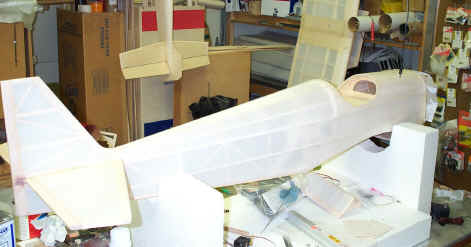
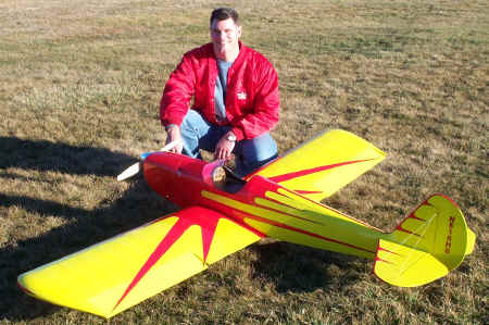 Finally had a great day to test fly the Sig 1/3 scale Spacewalker on
2-23-02 The dummy engine cylinders and painted pilot still need to be
installed. I never subject the pilot to the first flight. Joe Hartley
a.k.a brother in law was on hand for encouragement and pit duties. After
the G-45 finally belched to life it was time to head for the runway in the
moment of truth. The Spacewalker tracked straight with right rudder
and was airborne in about forty feet at 1/2 throttle. I was running a
Zinger 20 x 6-10 on the G45 which seemed to supply ample torque/ thrust
and a little rudder is needed on takeoffs. The plane slows down to a nice
gentle approach on landings and floats in like a big pussycat. A long time
consuming project since I chose the painted finish but well worth it. Sig
kits in my opinion contain high quality materials and are well engineered
to provided the modeler with a great flying airplane.
Finally had a great day to test fly the Sig 1/3 scale Spacewalker on
2-23-02 The dummy engine cylinders and painted pilot still need to be
installed. I never subject the pilot to the first flight. Joe Hartley
a.k.a brother in law was on hand for encouragement and pit duties. After
the G-45 finally belched to life it was time to head for the runway in the
moment of truth. The Spacewalker tracked straight with right rudder
and was airborne in about forty feet at 1/2 throttle. I was running a
Zinger 20 x 6-10 on the G45 which seemed to supply ample torque/ thrust
and a little rudder is needed on takeoffs. The plane slows down to a nice
gentle approach on landings and floats in like a big pussycat. A long time
consuming project since I chose the painted finish but well worth it. Sig
kits in my opinion contain high quality materials and are well engineered
to provided the modeler with a great flying airplane. |
|
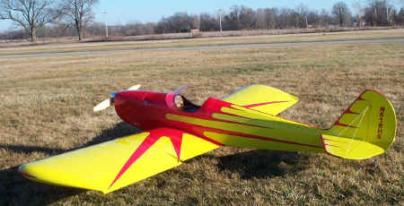 Another
view of the Sig 1/3 scale Spacewalker. Should look better when the dummy
engine cylinders are installed. Another
view of the Sig 1/3 scale Spacewalker. Should look better when the dummy
engine cylinders are installed.
|
|
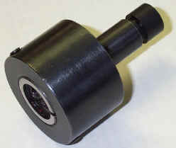
 A
fitting or coupler was made on the lathe to attach the cable to the servo
. The coupler was bored from each end to accept the cable and to fit over
the servo splines. 4-40 set screws are used to lock the coupler from
slippage. A
fitting or coupler was made on the lathe to attach the cable to the servo
. The coupler was bored from each end to accept the cable and to fit over
the servo splines. 4-40 set screws are used to lock the coupler from
slippage.
|
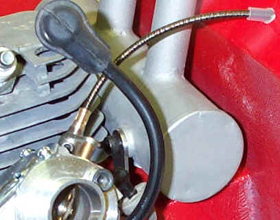 Since
the new carb rotating mount that Horizon Hobby is selling was backordered
I decided to go ahead with the original direct drive throttle linkage. The
Zenoah line of engines have always had the throttle linkage mounted at a
precarious angle that required bellcranks and multiple linkages to get
proper hookup. The direct drive hookup shown here is an alternative to
bellcranks/ linkages and the Zenoah carb adapter. Since
the new carb rotating mount that Horizon Hobby is selling was backordered
I decided to go ahead with the original direct drive throttle linkage. The
Zenoah line of engines have always had the throttle linkage mounted at a
precarious angle that required bellcranks and multiple linkages to get
proper hookup. The direct drive hookup shown here is an alternative to
bellcranks/ linkages and the Zenoah carb adapter.
A trip to the local auto store to buy speedometer cable and a few hours
at the lathe I came up with a direct drive linkage. The hardest part of
the linkage was figuring out how to terminate the cable to the throttle
arm. Steel rod was turned down and drilled to fit over the throttle stem
and a brass rod was brazed into the other end and drilled to accept the
cable. The cable was permanently swaged inside of the brass rod/sleeve.
The steel rod that fits over the throttle stem was drilled to accept a
4-40 Allen set screw. A similar termination will attach the serve at the
other end of the cable. |
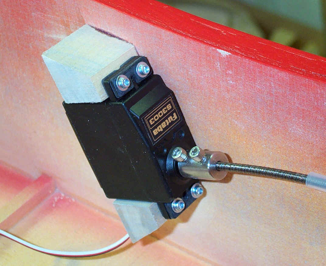
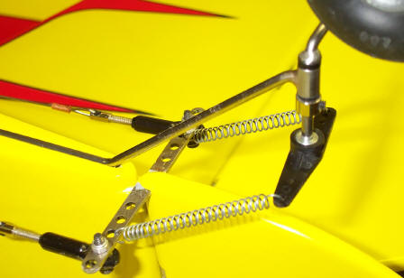
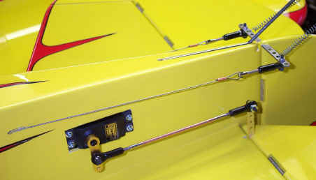 2
Futaba 9202 servos will control the elevator while a JR 8411 on pull
pull cables will provide the torque for the rudder. The Hangar 9 servo arm
on the 9202 will be trimmed or a shorter arm will be purchased. The
linkages are Rocket City 4-40 Ball Links with custom made 1/8" 4-40
pushrods. The retaining nut on the horn will be replaced by a locking
nut once the final setup/ratio has been achieved. By using an inner hole
on the servo arm and an outer hole on the control horn more leverage will
result thereby increasing the torque that the elevator sees. Sort of a
gear effect. I like to utilize the full travel of a servo and adjust the
linkages mechanically to achieve the correct throws. 2
Futaba 9202 servos will control the elevator while a JR 8411 on pull
pull cables will provide the torque for the rudder. The Hangar 9 servo arm
on the 9202 will be trimmed or a shorter arm will be purchased. The
linkages are Rocket City 4-40 Ball Links with custom made 1/8" 4-40
pushrods. The retaining nut on the horn will be replaced by a locking
nut once the final setup/ratio has been achieved. By using an inner hole
on the servo arm and an outer hole on the control horn more leverage will
result thereby increasing the torque that the elevator sees. Sort of a
gear effect. I like to utilize the full travel of a servo and adjust the
linkages mechanically to achieve the correct throws.
|
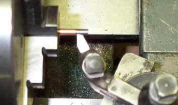
 This tool
is a die holder that was made to be installed in a lathe tailstock. The
end was cut shorter and a Delrin bushing was installed to guide the 1/8"
rod while hand threading. This tool
is a die holder that was made to be installed in a lathe tailstock. The
end was cut shorter and a Delrin bushing was installed to guide the 1/8"
rod while hand threading. |
 Before the
.125 rod can be threaded it needs to be turned down to .112 Turning the
rod down to .110 allows suitable threads for the Rocket City
Ball Links and allows for easier threading. Before the
.125 rod can be threaded it needs to be turned down to .112 Turning the
rod down to .110 allows suitable threads for the Rocket City
Ball Links and allows for easier threading. |
 The
tail wheel leaf spring was replaced by a custom made music wire assembly.
The vertical axle support is machined drill rod with Delrin bushings
brazed to the spring replacement wire. The stock Nylon tiller arm was used
along with the stock springs. This assembly is not scale but is looks
cleaner for a sport plane. The pull pull cables are 1/32 stainless steel
swaged with the proper tool to withstand the cable breaking strength. The
cables are also bushed with heat shrink tube where they enter the
turnbuckle. The
tail wheel leaf spring was replaced by a custom made music wire assembly.
The vertical axle support is machined drill rod with Delrin bushings
brazed to the spring replacement wire. The stock Nylon tiller arm was used
along with the stock springs. This assembly is not scale but is looks
cleaner for a sport plane. The pull pull cables are 1/32 stainless steel
swaged with the proper tool to withstand the cable breaking strength. The
cables are also bushed with heat shrink tube where they enter the
turnbuckle.
|
|
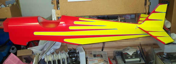
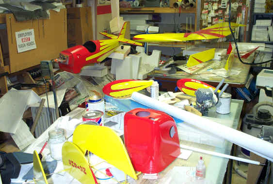 Here is a picture of the Sig 1/3
Spacewalker in pieces after painting. The components are painted separately
and assembled after buffing. The dummy engine cylinders still need to be
added to the cowling. I felt that it would be easier to add these after
painting in order to save some masking. The cylinders will be painted
before they are installed in the cowling. Here is a picture of the Sig 1/3
Spacewalker in pieces after painting. The components are painted separately
and assembled after buffing. The dummy engine cylinders still need to be
added to the cowling. I felt that it would be easier to add these after
painting in order to save some masking. The cylinders will be painted
before they are installed in the cowling.
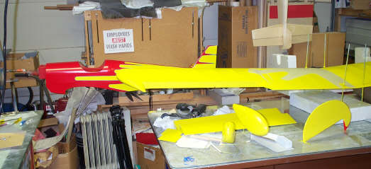
Recommended
Engines: For the 1/3 Scale Spacewalker
1.5-2.4 cu. in. 2-Stroke
1.8-3.0 cu. in. 4-stroke
Wingspan: 104 in.
Wing Area: 1800 sq. in.
Weight: 20 lbs. (I hope this ones comes out at 20#)
Length: 72 in.
Radio Required:4-Channel
|
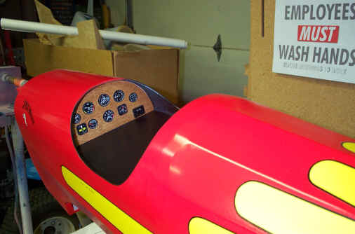
| The instrument panel installed in the
fuselage was constructed from Sig ply with a coat of stain
and satin polyurethane.
The sign in the background is a joke.
|
 |
| This picture shows the Sig
1/3 Scale Spacewalker fuselage before the 3M fine line tape has been removed. I
have learned to wait until the paint is dry for about four hours or more before
it is removed. It seems that I get a better edge with out tearing the
rubbery paint film if it is good and dry. Once the tape is removed I knock
the edge off of the paint with a piece of see temp or charge card. Also wet sanding with
1000 or 1500 grit will take the raised edge down. I used the 3M blue flexible tape since
it would go around the 1 1/4 inch radius for the scallops on the fuselage.
The paint is Sig Dope. Tennessee Red and Lemon Yellow. The red and
yellow are not scale but it shows up better and adds some pizzaz to the scheme. |
|
 The
wing and wheel pants still need the red trim added. Note the See Temp on
the wing as a guide for masking the pattern on the wing. Although the see temp
doesn't cover the whole scalloped pattern the pattern is enough to guide
the tape to a point. A See Temp pattern was
cut using the paint scheme drawn on the plans and is used as a guide for
applying the 3M fine line tape. The nice thing about the pattern for applying
the tape is you can flip the pattern over to do the opposing surfaces thereby
insuring a symmetrical paint scheme. I built the wing as one piece since I have
the trailer to haul it in. This made covering and painting a little more
of a challenge than if it was in three sections like the plans call for but has
saved considerable weight.
Since the wing will be bolted to the fuselage in the traditional manner it
allowed me to use threaded rod and nuts to suspend it while painting. This
allowed the wing to be flipped so that both sides could be painted. The
wing and wheel pants still need the red trim added. Note the See Temp on
the wing as a guide for masking the pattern on the wing. Although the see temp
doesn't cover the whole scalloped pattern the pattern is enough to guide
the tape to a point. A See Temp pattern was
cut using the paint scheme drawn on the plans and is used as a guide for
applying the 3M fine line tape. The nice thing about the pattern for applying
the tape is you can flip the pattern over to do the opposing surfaces thereby
insuring a symmetrical paint scheme. I built the wing as one piece since I have
the trailer to haul it in. This made covering and painting a little more
of a challenge than if it was in three sections like the plans call for but has
saved considerable weight.
Since the wing will be bolted to the fuselage in the traditional manner it
allowed me to use threaded rod and nuts to suspend it while painting. This
allowed the wing to be flipped so that both sides could be painted.
|
|
|
| The Spacewalker fuselage
covered with Sig
Koverall. The Koverall was applied with Sig Stixit and the first coat of Nitrate
Dope was brushed on with additional coats of nitrate applied to the seams
between sanding with 320 to knock off the fuzz at the seams. The next two coats of dope were Sig Supercoat clear
thinned 100% and sprayed on with an automotive touch up gun. After the
second coat was sprayed the covering started to take on a sheen. The
Automotive Acrylic Primer will be sprayed on next. The primer will be
sanded until the grain of the weave is filled.
Filling the weave with primer will still allow the
weave to show through once the dope cures in the sun. By sanding and
buffing the paint before it has completely cured (about four weeks) you
can achieve the best of both worlds, a shinny finish with a little weave
showing through for a scale appearance.
|
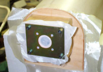
| The glassing of the Spacewalker
nose. The glass was applied to the front and sides of the engine box
and draped across the firewall. The engine plate was mounted with
Sig Koverall between the plate and the glass. The engine plate was
used to hold the glass against the firewall and the Sig Koverall is used
as a peel ply. Peel ply is used as a release so that the mounting
plate is not glued to the firewall. |
 |
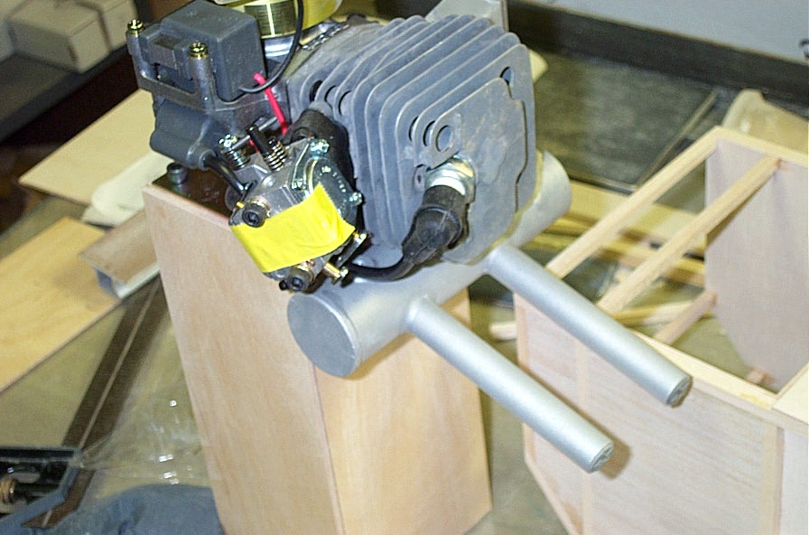 |
Zenoah
G-45 bolted to the engine box. Since the engine box construction has
worked well on the large IMAC airplanes it should do fine on a Sig 1/3 scale
Spacewalker.
|
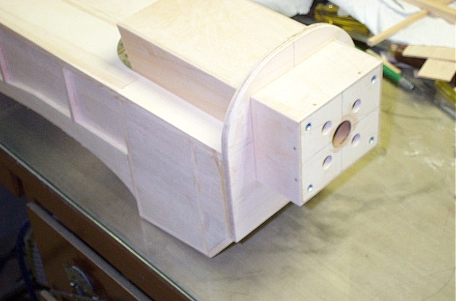
| The engine box glued into the firewall of the Sig Spacewalker. The
inside of the box has been glassed and the outside will be glassed also.
The firewall of the box has also been pinned to the sides of the box with 1/16
music wire. |
 |
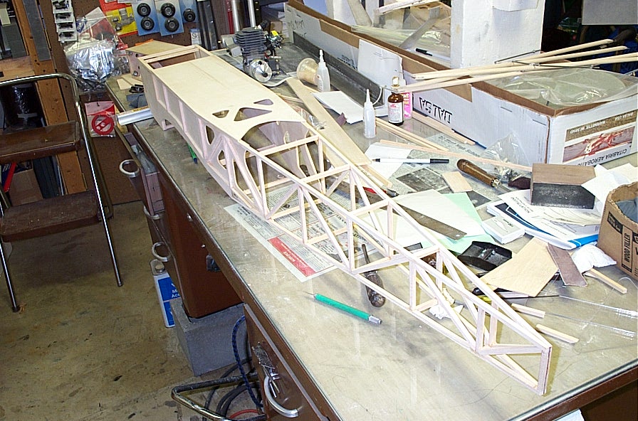 |
The
framed up fuselage ready for turtle deck formers and side stringers. In
order to get matching sides they were built one on top of the other with wax
paper separating them.
|
|
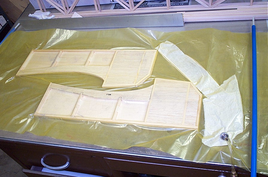
I have found it beneficial to vacuum bag parts with large surface
areas. Epoxy seems to be the adhesive of choice when vacuum bagging.
The picture shows the fuse sides bagged to the light plywood doublers.
|
 |
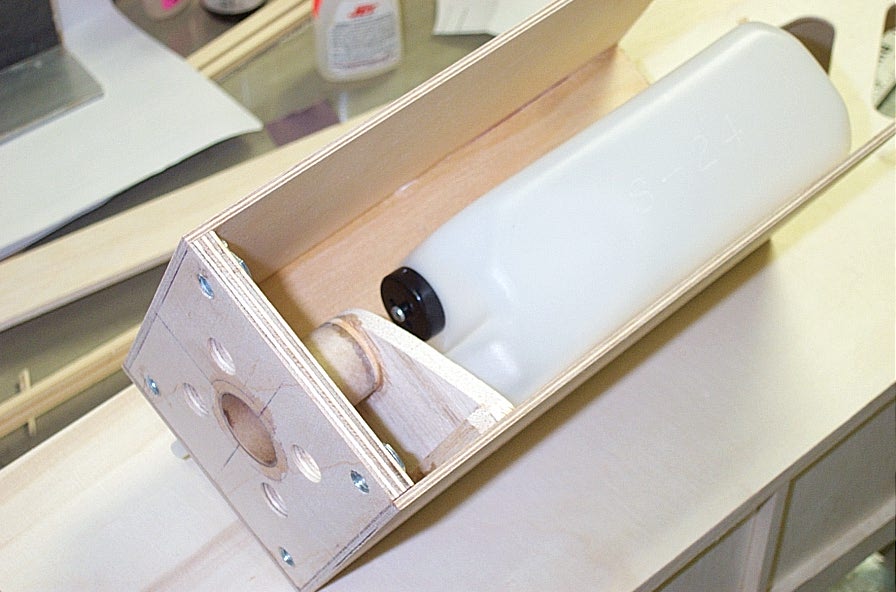 |
The
engine box before the last side is glued on. There is a tank bulkhead to
keep the tank away from the mounting screws protruding through the
firewall. The inside of the engine box was glassed at the seams.
|
|